Difference between revisions of "Precision Pendulum"
| Line 27: | Line 27: | ||
In front of the photodiode a solid-state laser beam from a normal pointer device is used to trigger the counter once the ball hide the light. | In front of the photodiode a solid-state laser beam from a normal pointer device is used to trigger the counter once the ball hide the light. | ||
| + | |||
| + | ===Non-remote usage=== | ||
| + | For local use the gate system can drive a up/down counter. Currently we have adopted the Velleman multifunction up/down counter kit K8035 avaiable off-the-shelf. The connection to the photo-diode is done via the VCC to the UP channel (pin 9) using just the first (R14) 2,2k resistor and eliminating the protection circuit in the transistor's gate(ZD1, R15 and R18). | ||
| + | The device should operate with ''Long debounce'' enable. Moreover we can use the regulated power supply (5V) in series with a 33 Ohms resistor to feed the photogate laser pointing device. | ||
Revision as of 18:27, 8 May 2013
An accurate pendulum is easy to construct once we get the right materials. The World Pendulum was design in a very robust way but a simplified version with common materials is described here.
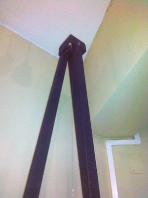
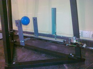
The basic support can be a wall or a robust metallic structure like the one presented here. The choice for the mass was a training steel weight from the official shot put with 2kg. This weight has the advantage of having a drilled hole for holding a M4 screw and can be find in any good sports shop. This screw can be made of a threaded brass rod with 10mm length. A small 1mm hole is drilled on the rod were the pendulum string is soldered using current soldering thin-plumb(or any silver-thin alloy). The string used is from 0.4mm remanium wire that can be bought in any dentistry retailer. The other end is soldered to the same brass rod with a length of 50mm, using the same technique (1mm hole and soldering).
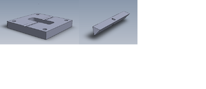
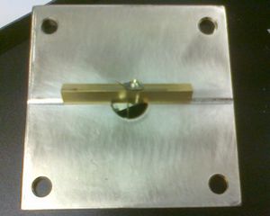
The support for the fulcrum is made from any robust plane surface as for instance a brass or stainless steel piece with a 12-16mm hole. This surface have a scratch made with a diamond or hard steel blade were the pivot work. With this design slipper is avoid.
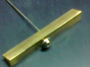
The fulcrum itself is made as well of stainless steel or brass consisting in a triangular pyramid with 50mmx9mm with a central 1mm hole in one face crossing the opposite edge. In this hole is soldered a intravenous needle were the pendulum string is glued or soldered.
Partners
Mechanical structures in suport of high schools replicas have been assembled and constructed with the kind help of CENFIM, Lisbon.

String measurement
The pendulum accuracy depends strongly in it's rigorous length measurement (2,700 m). Indeed this is the crucial factor to achieve the desired 0,02% accuracy and for that propose a well calibrated measuring tape as to be chose. If this method is adopted special care as to be taken to avoide parallax. Alternative methods like ultrasonic measurement with laser targeting are the best, using a metallic or marble stone plane fitted tangential to the weight (allowing it to roll but touching the plane). With this method a few takes shall be done surrounding the ball and their average value will be considered the pendulum reference length.
Recalibration of the length as to be pursuit every month to guarantee a reasonable precision.
Gate system
To avoid a long run of the experiment to achieve a reasonable period accuracy readout with a normal chronometer one could use instead a gated photo-detector connected to an acquisition system or to a precision pulse counter.
The World Pendulum design can be easily adapted as it consists on a photodiode mounted in a aluminium holder (20x20x6 mm3) with a central 1,5mm hole and a 4mm cavity on the back side(see design) where is fixed the photodiode with a black plastic wax.
In front of the photodiode a solid-state laser beam from a normal pointer device is used to trigger the counter once the ball hide the light.
Non-remote usage
For local use the gate system can drive a up/down counter. Currently we have adopted the Velleman multifunction up/down counter kit K8035 avaiable off-the-shelf. The connection to the photo-diode is done via the VCC to the UP channel (pin 9) using just the first (R14) 2,2k resistor and eliminating the protection circuit in the transistor's gate(ZD1, R15 and R18). The device should operate with Long debounce enable. Moreover we can use the regulated power supply (5V) in series with a 33 Ohms resistor to feed the photogate laser pointing device.
