Difference between revisions of "Angular Momentum Conservation"
m (Text replacement - "|left" to "|center") |
|||
| (31 intermediate revisions by 3 users not shown) | |||
| Line 1: | Line 1: | ||
| − | + | =Description of the Experiment= | |
| + | This control room allows the confirmation of angular momentum conservation by making collide a spinning disk with another one. Beyond that, the disk inertia momentum can be extrapolated based on the principles of conservation of energy. | ||
| + | |||
| + | <!-- Acho que este texto não está muito correcto. --> | ||
| + | |||
| + | |||
| + | <div class="toccolours mw-collapsible mw-collapsed" style="width:420px"> | ||
| + | '''Links''' | ||
| + | <div class="mw-collapsible-content"> | ||
| + | |||
| + | *Video: rtsp://elabmc.ist.utl.pt/inertiadisks.sdp | ||
| + | *Laboratory: Intermediate in [http://e-lab.ist.eu e-lab.ist.eu] | ||
| + | *Control room: [unavaliable] | ||
| + | *Level: *** | ||
| + | |||
| + | </div> | ||
| + | </div> | ||
| + | |||
| + | {{#ev:youtube|X2OK3akY4GE|Slow motion video (12x) of the discs connecting.|center}} | ||
| − | |||
| − | |||
=Experimental Apparatus= | =Experimental Apparatus= | ||
| − | The experimental apparatus is based | + | The experimental apparatus is based on a PC hard disk drive motor and its spinning disc with a mass of 115g, 12.5mm internal radius and 47.5mm external. A second disc with a mass of 69g and the same dimensions is held on top of it and can be dropped by a servo motor actuator. |
| + | |||
| + | The motor of the apparatus can be used as a generator equipped with a switchable resistor, acting as an electromagnetic brake. The braking current and the voltage characteristic are measured allowing an accurate calculation of energy dissipation. | ||
| − | |||
=Protocol - Angular Momentum Conservation= | =Protocol - Angular Momentum Conservation= | ||
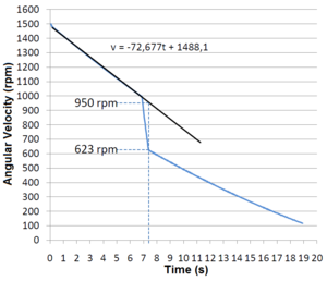
| − | [[File: | + | [[File:Discs_velocity_protocol1.png|thumb|alt=|Figure 1: Angular velocity (rpm) as a function of time for a collision at 1000 rpm.]] |
| − | The bottom disc is accelerated by the motor until it reaches a selected angular velocity. | + | The bottom disc is accelerated by the motor until it reaches a selected angular velocity. At this point, the engine is disconnected from power and the disc is allowed to rotate freely. When a certain pre-determined velocity is reached, the servo lets the suspended disc initially at rest fall on top of the rotating disc. |
Data taken from the experiment is given and plotted with the disc velocity in function of time. | Data taken from the experiment is given and plotted with the disc velocity in function of time. | ||
| − | '''Figure1''' is a plot of the results of an | + | '''Figure1''' is a plot of the results of an experiment in which a servo lets the suspended disc fall when the disc below reaches 1000 rpm. |
| + | |||
| + | Doing a linear regression between the deceleration and the fall of the disc, it is possible to obtain the predicted velocity at any time. This gives us the rule of thumb of the friction deceleration related to angular velocity. | ||
| − | |||
| − | = | + | =Advanced Protocol - Moment of Inertia Evaluation= |
| − | Using the | + | |
| + | [[File:Discos_velocidade_protocolo2.png|thumb|alt=|Figure2: Rotational velocity as function of time after the electromagnetic breaking.|right|border|240px]] | ||
| + | [[File:Discos_tensao_2fases.png|thumb|alt=|Figure3: Circuit schematic for voltage measurement.|right|border|240px]] | ||
| + | [[File:Discos_tensao.png|thumb|alt=|Figure4: Voltage between two phases during breaking.|right|border|240px]] | ||
| + | [[File:W_extrap.gif|thumb|alt=|Figure5: Extrapolation of w based on the initial slope of deceleration.|right|border|240px]] | ||
| + | [[File:Discos_balanco_energetico.png|thumb|alt=|Figure6: Final energy balance showing electrical and mechanical component allowing you to get the total moment of inertia.|right|border|240px]] | ||
| + | |||
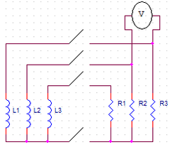
| + | The bottom disc is accelerated by the motor to a selected angular velocity. At that time the motor supply is disconnected and the disc is allowed to rotate freely. When a certain pre-determined velocity is reached, a relay puts each motor winding in parallel with a resistor resistance similar to the windings of the motor ('''Picture 3'''). These resistors will dissipate energy, acting as an electromagnetic brake. Voltage and velocity as functions of time are given in a table of results at the end of the session. | ||
| + | |||
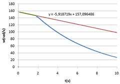
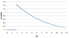
| + | '''Figures 2''' and '''4''' are plots obtained through the table of results of an experiment in which the relay turns on when the rotating discs reach 1400 rpm. | ||
| + | |||
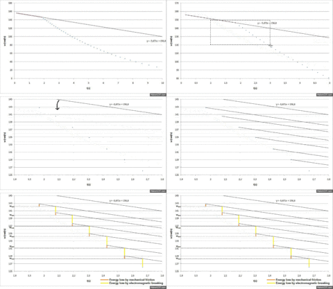
| + | Using the first data from '''Figure 2''', before the braking, to do a linear regression, you can get the angular deceleration caused by friction, assumed constant all the time, from the slope of the line. From this deceleration it will be possible to calculate the instantaneous loss of angular momentum deferentially. | ||
| + | |||
| + | Between each speed acquisition an energy balance is done . The loss of total mechanical energy must be equal to the sum of losses by friction and electromagnetic breaking. | ||
| − | + | <math> \Delta E_{mec} = \Delta E_{friction} + \Delta E_{elec}</math> | |
| − | I | + | The energy of a rotating body is <math> E_{rot}=\frac{I w^2}{2}</math> I being the moment of inertia. Then, the variation of mechanical energy between each acquisition will be: |
| − | + | <math>\Delta E_{mec}=\frac{I(w_{n+1}^2-w_{n}^2)}{2}</math> | |
| − | + | <math>w_{n+1}</math> and <math>w_{n}</math> being the angular velocity in two consecutive acquisitions. | |
| − | + | Using the initial slope of deceleration <math>a</math> due to mechanical friction, one can extrapolate <math>w_{n+1}</math> in absence of electromagnetic breaking. | |
| − | + | <math>w_{n+1}= w_{n} + a \Delta t</math> | |
| − | + | Substituting this extrapolated <math>w_{n+1}</math> in the equation of total energy variation it is possible to calculate the energy dissipation due to mechanical friction: | |
| − | + | <math>\Delta E_{friction}=\frac{I(w_{n}^2+2w_{n}a\Delta t + a^2\Delta t^2-w_{n}^2)}{2}</math> | |
| − | + | <math>\Delta E_{friction}=\frac{I(2w_{n}a\Delta t + a^2\Delta t^2)}{2}</math> | |
| − | + | A set of extrapolations of <math>w_{n+1}</math> can be seen in '''Figure 5'''. | |
| − | The | + | The dissipated power is: |
| − | + | <math>P=VI=\frac{V^2}{R}</math> | |
| − | + | The rms voltage across one winding is: | |
| − | + | <math>V_{rms}=\frac{V_{measured}}{\sqrt{3}\sqrt{2}}</math> | |
| − | + | In the setup used, the energy dissipates in 3 branches, so the power comes multiplied by 3. Besides, each winding is in parallel with a resistor with the same resistance value <math>4,7\Omega</math>, which means the power equation will come multiplied by 2 and <math>R=4,7\Omega</math> will be used. | |
| − | + | <math>P=3\times2\times\frac{V_{rms}^2}{R}=3\times2\times\left(\frac{V_{measured}}{\sqrt{3}\sqrt{2}}\right)^2\frac{1}{R}</math> | |
| − | + | <math>P=\frac{V^2}{R}</math> | |
| − | + | The energy dissipated will be: | |
| − | + | <math>\Delta E_{ele}=P*\Delta t</math> | |
| − | + | Where <math>\Delta t</math> is the time between acquisitions. | |
| − | + | The ballance between each consecutive acquitition is summed in the end. | |
| − | + | <math>Balance = \Delta E_{mec} - \Delta E_{friction} - \Delta E_{elec}</math> | |
| − | + | Finally the goal-seek function of Microsoft Excel is used to force the sum of balances to be 0 (zero) changing the value of I. | |
| − | + | Using this method, we reached an experimental value of <math>1,274\times10^{-4} kg m^2</math> for the moment of inertia. | |
| − | |||
| − | |||
| − | |||
| − | + | '''Figure 6''' shows the energy of the disc in function of time, the energy lost by friction and electromagnetic breaking and the sum of all the energies that allows the verification of the conservation of energy throughout the experiment. | |
| − | + | The disc is in fact a ring having an interior radius of 13mm and an exterior radius of 47mm, so its theoretical moment of inertia is: | |
| − | + | <math>I=\frac{m\left(r_1^2+r_2^2\right)}{2}=\frac{0,115\left(0,013^2+0,047^2\right)}{2}=1,367\times 10^{-4}kg \; m^2</math> | |
| − | + | Evaluating the accuracy: | |
| − | + | <math>\frac{\left|1,274\times 10^{-4}-1,367\times 10^{-4}\right|}{\left|1,367\times 10^{-4}\right|}\times 100=6,8\%</math> | |
| − | + | This experiment gave results that differ by '''6,8%''' from the ones calculated theoretically. | |
| − | + | =Physics= | |
| + | Using the following quantities: | ||
| − | + | L - angular momentum | |
| − | + | I - moment of inertia | |
| − | + | ω - angular velocity | |
| − | + | m - mass in rotation. | |
| − | + | For the angular momentum conservation: | |
| − | + | <math>L_i=L_f</math> | |
| − | + | <math>I_i \omega_i=I_f \omega_f</math> | |
| − | + | <math>\frac{I_i}{I_f}=\frac{\omega_f}{\omega_i}</math> | |
| − | + | <math>\frac{\frac{m_i\left (r_1^2+r_2^2 \right )}{2}}{\frac{m_f\left (r_1^2+r_2^2 \right )}{2}}=\frac{\omega_f}{\omega_i}</math> | |
| − | + | <math>\frac{m_i}{m_f}=\frac{\omega_f}{\omega_i}</math> | |
| − | + | The experimental results give: | |
| − | + | <math>\frac{\omega_f}{\omega_i}=\frac{623}{950}=0,656</math> | |
| − | + | while the predicted mass ratio is | |
| − | + | <math>\frac{m_i}{m_f}=\frac{115}{115+69}=0,625</math> | |
| − | + | Evaluating the accuracy: | |
| − | + | <math>\frac{\left|0,656-0,625\right|}{\left|0,625\right|}\times 100=4,9\%</math> | |
| − | + | The speed ratio is different from the mass ratio by 4,9%, which gives a good approximation of the angular momentum conservation. | |
| − | + | Knowing the exact dimensions of the disks (<math>r_1=12,5mm, r_2=47,5mm</math>) and adding an error momentum to the equations, you can infer an approximated value of the motor rotor momentum of inertia (or its mass knowing its average radius). | |
| − | + | <math>I_i \omega_i=I_f \omega_f</math> | |
| − | + | <math>\left (I_m + I_{Di}\right ) \omega_i=\left (I_m + I_{Df}\right ) \omega_f</math> | |
| − | + | Solving in for <math>I_m</math> | |
| − | + | <math>I_m = \frac{I_{Df} \omega_f - I_{Di} \omega_i}{\omega_i-\omega_f}</math> | |
| − | |||
| − | + | =Links= | |
| + | *[[Conservação do Momento Angular | Portuguese version (Versão em Português)]] | ||
Latest revision as of 14:12, 28 May 2015
Contents
Description of the Experiment
This control room allows the confirmation of angular momentum conservation by making collide a spinning disk with another one. Beyond that, the disk inertia momentum can be extrapolated based on the principles of conservation of energy.
Links
- Video: rtsp://elabmc.ist.utl.pt/inertiadisks.sdp
- Laboratory: Intermediate in e-lab.ist.eu
- Control room: [unavaliable]
- Level: ***
Experimental Apparatus
The experimental apparatus is based on a PC hard disk drive motor and its spinning disc with a mass of 115g, 12.5mm internal radius and 47.5mm external. A second disc with a mass of 69g and the same dimensions is held on top of it and can be dropped by a servo motor actuator.
The motor of the apparatus can be used as a generator equipped with a switchable resistor, acting as an electromagnetic brake. The braking current and the voltage characteristic are measured allowing an accurate calculation of energy dissipation.
Protocol - Angular Momentum Conservation
The bottom disc is accelerated by the motor until it reaches a selected angular velocity. At this point, the engine is disconnected from power and the disc is allowed to rotate freely. When a certain pre-determined velocity is reached, the servo lets the suspended disc initially at rest fall on top of the rotating disc.
Data taken from the experiment is given and plotted with the disc velocity in function of time.
Figure1 is a plot of the results of an experiment in which a servo lets the suspended disc fall when the disc below reaches 1000 rpm.
Doing a linear regression between the deceleration and the fall of the disc, it is possible to obtain the predicted velocity at any time. This gives us the rule of thumb of the friction deceleration related to angular velocity.
Advanced Protocol - Moment of Inertia Evaluation
The bottom disc is accelerated by the motor to a selected angular velocity. At that time the motor supply is disconnected and the disc is allowed to rotate freely. When a certain pre-determined velocity is reached, a relay puts each motor winding in parallel with a resistor resistance similar to the windings of the motor (Picture 3). These resistors will dissipate energy, acting as an electromagnetic brake. Voltage and velocity as functions of time are given in a table of results at the end of the session.
Figures 2 and 4 are plots obtained through the table of results of an experiment in which the relay turns on when the rotating discs reach 1400 rpm.
Using the first data from Figure 2, before the braking, to do a linear regression, you can get the angular deceleration caused by friction, assumed constant all the time, from the slope of the line. From this deceleration it will be possible to calculate the instantaneous loss of angular momentum deferentially.
Between each speed acquisition an energy balance is done . The loss of total mechanical energy must be equal to the sum of losses by friction and electromagnetic breaking.
[math] \Delta E_{mec} = \Delta E_{friction} + \Delta E_{elec}[/math]
The energy of a rotating body is [math] E_{rot}=\frac{I w^2}{2}[/math] I being the moment of inertia. Then, the variation of mechanical energy between each acquisition will be:
[math]\Delta E_{mec}=\frac{I(w_{n+1}^2-w_{n}^2)}{2}[/math]
[math]w_{n+1}[/math] and [math]w_{n}[/math] being the angular velocity in two consecutive acquisitions.
Using the initial slope of deceleration [math]a[/math] due to mechanical friction, one can extrapolate [math]w_{n+1}[/math] in absence of electromagnetic breaking.
[math]w_{n+1}= w_{n} + a \Delta t[/math]
Substituting this extrapolated [math]w_{n+1}[/math] in the equation of total energy variation it is possible to calculate the energy dissipation due to mechanical friction:
[math]\Delta E_{friction}=\frac{I(w_{n}^2+2w_{n}a\Delta t + a^2\Delta t^2-w_{n}^2)}{2}[/math]
[math]\Delta E_{friction}=\frac{I(2w_{n}a\Delta t + a^2\Delta t^2)}{2}[/math]
A set of extrapolations of [math]w_{n+1}[/math] can be seen in Figure 5.
The dissipated power is:
[math]P=VI=\frac{V^2}{R}[/math]
The rms voltage across one winding is:
[math]V_{rms}=\frac{V_{measured}}{\sqrt{3}\sqrt{2}}[/math]
In the setup used, the energy dissipates in 3 branches, so the power comes multiplied by 3. Besides, each winding is in parallel with a resistor with the same resistance value [math]4,7\Omega[/math], which means the power equation will come multiplied by 2 and [math]R=4,7\Omega[/math] will be used.
[math]P=3\times2\times\frac{V_{rms}^2}{R}=3\times2\times\left(\frac{V_{measured}}{\sqrt{3}\sqrt{2}}\right)^2\frac{1}{R}[/math]
[math]P=\frac{V^2}{R}[/math]
The energy dissipated will be:
[math]\Delta E_{ele}=P*\Delta t[/math]
Where [math]\Delta t[/math] is the time between acquisitions.
The ballance between each consecutive acquitition is summed in the end.
[math]Balance = \Delta E_{mec} - \Delta E_{friction} - \Delta E_{elec}[/math]
Finally the goal-seek function of Microsoft Excel is used to force the sum of balances to be 0 (zero) changing the value of I.
Using this method, we reached an experimental value of [math]1,274\times10^{-4} kg m^2[/math] for the moment of inertia.
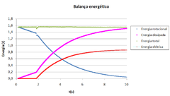
Figure 6 shows the energy of the disc in function of time, the energy lost by friction and electromagnetic breaking and the sum of all the energies that allows the verification of the conservation of energy throughout the experiment.
The disc is in fact a ring having an interior radius of 13mm and an exterior radius of 47mm, so its theoretical moment of inertia is:
[math]I=\frac{m\left(r_1^2+r_2^2\right)}{2}=\frac{0,115\left(0,013^2+0,047^2\right)}{2}=1,367\times 10^{-4}kg \; m^2[/math]
Evaluating the accuracy:
[math]\frac{\left|1,274\times 10^{-4}-1,367\times 10^{-4}\right|}{\left|1,367\times 10^{-4}\right|}\times 100=6,8\%[/math]
This experiment gave results that differ by 6,8% from the ones calculated theoretically.
Physics
Using the following quantities:
L - angular momentum
I - moment of inertia
ω - angular velocity
m - mass in rotation.
For the angular momentum conservation:
[math]L_i=L_f[/math]
[math]I_i \omega_i=I_f \omega_f[/math]
[math]\frac{I_i}{I_f}=\frac{\omega_f}{\omega_i}[/math]
[math]\frac{\frac{m_i\left (r_1^2+r_2^2 \right )}{2}}{\frac{m_f\left (r_1^2+r_2^2 \right )}{2}}=\frac{\omega_f}{\omega_i}[/math]
[math]\frac{m_i}{m_f}=\frac{\omega_f}{\omega_i}[/math]
The experimental results give:
[math]\frac{\omega_f}{\omega_i}=\frac{623}{950}=0,656[/math]
while the predicted mass ratio is
[math]\frac{m_i}{m_f}=\frac{115}{115+69}=0,625[/math]
Evaluating the accuracy:
[math]\frac{\left|0,656-0,625\right|}{\left|0,625\right|}\times 100=4,9\%[/math]
The speed ratio is different from the mass ratio by 4,9%, which gives a good approximation of the angular momentum conservation.
Knowing the exact dimensions of the disks ([math]r_1=12,5mm, r_2=47,5mm[/math]) and adding an error momentum to the equations, you can infer an approximated value of the motor rotor momentum of inertia (or its mass knowing its average radius).
[math]I_i \omega_i=I_f \omega_f[/math]
[math]\left (I_m + I_{Di}\right ) \omega_i=\left (I_m + I_{Df}\right ) \omega_f[/math]
Solving in for [math]I_m[/math]
[math]I_m = \frac{I_{Df} \omega_f - I_{Di} \omega_i}{\omega_i-\omega_f}[/math]
