Difference between revisions of "Physical Pendulum"
(Created page with "=Experiment Description= A physical pendulum consists of a rigid body that undergoes fixed axis rotation about a fixed point. In the present case it has a rigid rod structure...") |
|||
| (8 intermediate revisions by the same user not shown) | |||
| Line 1: | Line 1: | ||
=Experiment Description= | =Experiment Description= | ||
| − | |||
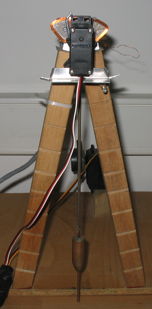
| − | The purpose of this experiment is to verify how the pendulum's motion varies with the length between the fulcrum and the | + | [[File: PenduloGravitico.png| thumb | Physical pendulum made up of a rigid shaft and a bob that can slide in height]] |
| + | |||
| + | A physical pendulum consists of a rigid body that undergoes fixed axis rotation about a fixed point. In the present case it has a rigid rod structure and a mass (bob) whose position can vary from 152mm to 248mm. | ||
| + | |||
| + | The purpose of this experiment is to verify how the pendulum's motion varies with the length between the fulcrum and the bob position and its damped factor according to the initial displacement (the same is to say the initial energy). | ||
| Line 9: | Line 12: | ||
<div class="mw-collapsible-content"> | <div class="mw-collapsible-content"> | ||
| − | *Video: rtsp://elabmc.ist.utl.pt/.sdp | + | *Video: rtsp://elabmc.ist.utl.pt/pendulogravitico.sdp |
| − | *Laboratory: Basic in e-lab.ist. | + | *Laboratory: Basic in e-lab.ist.utl.pt[http://e-lab.ist.utl.pt] |
| − | *Control room: | + | *Control room: Gravity Pendulum |
*Grade: * | *Grade: * | ||
</div> | </div> | ||
</div> | </div> | ||
| − | |||
=Experimental Apparatus= | =Experimental Apparatus= | ||
| + | ==Description== | ||
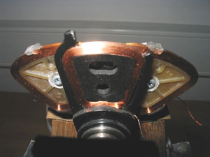
| + | [[File:PromenorSensorPenduloGravitico.png|thumb | Detail of the angular diferential sensor position based on hard-disk coils]] | ||
| − | This | + | This experiment consists on a pendulum composed by a variable position mass along a rigid rod. The pendulum's bob slides on the rod and it's possible to define the height of the mass over the rod. It's also possible to define the initial angle and the frequency for the acquisitions (sample rate) as the pendulum oscillates. |
| − | The | ||
| + | Historically pendulums are used since about the year 1600 and it's discovery and first studies are assigned to Galileo Galilei. Its regular oscillation allows it to be used to measure time quite accurately until very recently, and the fine tuning of its length allowed for regulating pendulum clocks very precisely. Pendulums were also used to perform the first measurements of the acceleration of gravity. | ||
| − | The | + | The experiment allows the pendulum to be launched from different initial angular positions and it is possible to choose the length of the pendulum rod and the sample rate to an upper time of 10 s. At the top of the pendulum rod is attached a magnetic head of a conventional hard disk that allows determining the angular position of the pendulum over time and infer the velocity by calculating its differential. |
| − | + | The apparatus is composed by a servo motor to position the bob over the a rod and another servo for the initial displacement induced to "launch" the experiment. | |
| − | + | == Specifications == | |
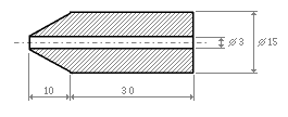
| − | + | [[File: grave.png | thumb | Drawing and dimensions of the bob]] | |
| − | |||
| + | * Variable length between 141 and 208 mm. | ||
| + | * Starting angle: from 1.5 to 13.5º. | ||
| + | * Expected oscillation frequencies ~1.03 to 1.26 Hz. | ||
| + | * Resolution: 0.1º. | ||
| + | * Semi-oscillation time: ~ 30 cycles (maximum length) and ~ 15 (minimum length) | ||
| + | * Maximum acquisition frequency of 106 Hz, with RS-232 communication at 38400 bits/s. | ||
| + | * Power supply: 12 V. | ||
| + | * Bob's mass : 51.16 ± 0.01 gr. | ||
| + | * Shaft mass: 18,46 ± 0,01 gr. | ||
| + | * Shaft dimensions: 275 mm in length, 3 mm in diameter. | ||
| + | * Distance from the base of the grave to the center of mass: 157 mm. | ||
=Protocol= | =Protocol= | ||
| − | The user must specify the | + | The user must specify the bob's position, the number of samples, the frequency between them and the initial angle. This last option indirectly defines the speed at which the experiment occurs. |
| − | |||
| − | |||
=Links= | =Links= | ||
| − | + | *[[Pêndulo de Haste Rígida| Portuguese version (Versão em Português)]] | |
| − | *[[ | ||
Latest revision as of 13:57, 4 March 2019
Contents
Experiment Description
A physical pendulum consists of a rigid body that undergoes fixed axis rotation about a fixed point. In the present case it has a rigid rod structure and a mass (bob) whose position can vary from 152mm to 248mm.
The purpose of this experiment is to verify how the pendulum's motion varies with the length between the fulcrum and the bob position and its damped factor according to the initial displacement (the same is to say the initial energy).
Links
- Video: rtsp://elabmc.ist.utl.pt/pendulogravitico.sdp
- Laboratory: Basic in e-lab.ist.utl.pt[1]
- Control room: Gravity Pendulum
- Grade: *
Experimental Apparatus
Description
This experiment consists on a pendulum composed by a variable position mass along a rigid rod. The pendulum's bob slides on the rod and it's possible to define the height of the mass over the rod. It's also possible to define the initial angle and the frequency for the acquisitions (sample rate) as the pendulum oscillates.
Historically pendulums are used since about the year 1600 and it's discovery and first studies are assigned to Galileo Galilei. Its regular oscillation allows it to be used to measure time quite accurately until very recently, and the fine tuning of its length allowed for regulating pendulum clocks very precisely. Pendulums were also used to perform the first measurements of the acceleration of gravity.
The experiment allows the pendulum to be launched from different initial angular positions and it is possible to choose the length of the pendulum rod and the sample rate to an upper time of 10 s. At the top of the pendulum rod is attached a magnetic head of a conventional hard disk that allows determining the angular position of the pendulum over time and infer the velocity by calculating its differential.
The apparatus is composed by a servo motor to position the bob over the a rod and another servo for the initial displacement induced to "launch" the experiment.
Specifications
- Variable length between 141 and 208 mm.
- Starting angle: from 1.5 to 13.5º.
- Expected oscillation frequencies ~1.03 to 1.26 Hz.
- Resolution: 0.1º.
- Semi-oscillation time: ~ 30 cycles (maximum length) and ~ 15 (minimum length)
- Maximum acquisition frequency of 106 Hz, with RS-232 communication at 38400 bits/s.
- Power supply: 12 V.
- Bob's mass : 51.16 ± 0.01 gr.
- Shaft mass: 18,46 ± 0,01 gr.
- Shaft dimensions: 275 mm in length, 3 mm in diameter.
- Distance from the base of the grave to the center of mass: 157 mm.
Protocol
The user must specify the bob's position, the number of samples, the frequency between them and the initial angle. This last option indirectly defines the speed at which the experiment occurs.


