Inclined Plane
Experiment description
The inclined plane is one of the six classic simple machines. Inclined planes are generally used to move heavy loads over vertical obstacles, such as ramps to move cargo.
Moving an object up on an inclined plane requires less force than lifting it vertically, as if we reduced gravity! This mechanical advantage, by which the force is reduced, is equal to the ratio between the length of the inclined surface and the height of the plane.
In laboratory experiments that recreate this machine, when an air chute is not used in order to almost eliminate the rolling friction, the plane must have a significant slope so that the gravitational acceleration can be much higher than the friction, making it impossible for this experience to be carried out in a long time, perceptible to human senses.
However, friction is an integral part of the mechanics of the problem. With this experiment, it is possible to determine the friction function through a multivariate analysis, adjusting a function that depends on the inclination of the rail. For this purpose, the experiment allows changing the descent angle and, through this, separating the frictional forces from the gravitational force, obtaining a value very close to 9,8 ms-2.
Links
- Video: rtsp://elabmc.ist.utl.pt/plinc.sdp
- Laboratory: Básico
- Control Room: Inclined Plane
- Level: *
Purposely, this experiment uses a car equipped with a frontal windshield in order to exacerbate the effect of friction and demonstrate that its equation can be determined by multivariate analysis of several rides, for different inclinations.
Experimental apparatus
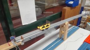
The inclined plane of this experiment recreates this "reduction of gravity". It consists of a vehicle that moves on a track with adjustable inclination and that tilts at its midpoint. The height of the chute is measured at 1003 mm from the axis of the experiment.
Initially the chute tilts to a position with a negative angle in order to collect and park the car at the origin, about 1.3 m from the spring that will absorb the energy of its movement. The electromagnet immobilizes the car and, subsequently, the rail is raised to the pre-selected height. When it reaches that point, the electromagnet releases the car and it moves freely on the rail until it hits the spring. An ultrasonic detector then collects position samples as a function of the elapsed time, allowing to trace the vehicle's trajectory during the fall and in its final damping.
(Um detector ultrasónico colhe, então, amostras da posição em função do tempo decorrido, permitindo traçar a trajectória do veículo durante a queda e no seu amortecimento final.)
Protocol
Based on the pre-selected data in the experiment, obtain a graph of the position as a function of the elapsed time. Based on this data, determine the speed and acceleration graphs. Compare the acceleration obtained value with gravity.
Determination of speed as a function of distance traveled
Based on the previous data, determine the speed as a function of the distance traveled eliminating the time in the previous graphs, that is, tracing the curve drawn by the speed pairs, distance for each available time.
Determination of the spring restitution constant
Depending on the various parables obtained in the vehicle's damping, determine the relative energy loss in each collision with the spring and determine the spring restitution constant.
Advanced protocol
As can be quickly inferred, the adjustment of the parabolic model to the movement produces a deviation that is only possible to understand with the inclusion of a friction term. In effect, the car has a front flap designed to induce a certain aerodynamic friction. By adapting the equations to include a rolling friction term (linear with velocity) and aerodynamic (Cx, quadratic dependence with velocity), a more accurate value for the acceleration of the vehicle can finally be determined. Usually the Cx only significantly influences the movement after 25 km/h.
The adjustment of a friction function for the acceleration in the form a = b + c*v + d*v2 allows to extract the local acceleration of gravity when using several sets of data for various angles.
Multivariate model
A análise multivariada utilizada serve para construir um modelo de ajuste numérido para vários ângulos às várias características do movimento obtido. A variação do ângulo permite distinguir o efeito da gravidade do da força de atrito de rolamento, já que este é considerado independente do ângulo. Deste modo, ao fazer um ajuste do tipo a = b + c*v + d*v2, o parâmetro b que detém implicitamente a gravidade e o atrito de rolamento (relacionado com a mecânica do veículo) pode ser resolvido separando-o em b=g*sin(θ) + batrito. Os restantes parâmetros resultam de um modelo da dependência do atrito com a velocidade. Para valores elevados desta (tipicamente superior a 7-10 ms-1), o atrito tem uma forte dependência quadrática com a velocidade – atrito aerodinâmico – mas, no nosso caso, também temos de considerar a dependência de atrito mecânico (batrito+c*v), uma vez que o carro parte do repouso.
Ao realizar esta análise multivariada estamos a considerar uma associação independente entre os parâmetros, condição necessária para esses parâmetros fazerem parte de um modelo numérico que se provará correto pelo desfecho do ajuste. Para o efeito, deverá ser utilizado um solver numérico ajustando interativamente as várias co-variáveis, tal como o do MSExcel.
Determinação rigorosa da constante de restituição da mola
Uma análise breve permite concluir que a constante de restituição da mola para os vários embates vem ferida de um erro apreciável, tanto maior quanto o percurso percorrido, uma vez que o trabalho realizado pela força de atrito prejudica o cálculo da energia mecânica em cada troço do movimento. No entanto, calculando o trabalho efetuado pela força de atrito com base na equação da força de atrito determinada pelo processo anteriormente descrito, é possível inferir corretamente a energia mecânica antes e depois de cada embate, permitindo calcular corretamente a constante de restituição da mola.
Pormenores da construção
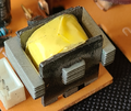
O componente mais curioso desta experiência é o eletroiman que mantém o carrinho seguro na posição de lançamento. Com efeito, este eletroiman pode ser construído enrolando fio esmaltado sobre um núcleo de ferro mole ou usando um eletroiman extraído duma simples torradeira! Outra inovação é a montagem ser efetuada sobre uma calha basculante que simplifica o recolher do carrinho à posição de lançamento. Como é necessário uma inclinação razoável para vencer o atrito estático, o embate no eletroiman de fixação é significativo mas pode ser resolvido colocando uma espuma autocolante em ambas as faces, entre o ferro de atracação e o carro.


