Angular Momentum Conservation
UNDER CONSTRUCTION
Contents
Description of the Experiment
This control room allows the confirmation of angular momentum conservation and the measuring of the moment of inertia of rotating discs.
Experimental Apparatus
The experimental apparatus is based in a PC hard-drive to which were added a servo and a group of discs that the servo keeps above the rotating discs. This setup allows the realization of the first protocol, centered in the study of angular momentum conservation.
The aparatus also has a group of braking resistors that can be connected in parallel with the motor windings. This setup allows the realization of the second protocol, centered in the study of the moment of inertia.
Protocol 1 - Angular Momentum Conservation
5 discs with a total mass of 115g are acelerated by the hard-drive motor until they reach 1500rpm. In this moment the motor is disconnected, the discs rotate freely and their speed is read. When a certain speed that the user defines previously is reached, the servo let's 3 suspended discs with a total mass of 69g initially at rest fall on top of the rotating discs.
In the end of the session a table is provided with the disc speed function of time, whose values will be used in a plot created in some program the user chooses.
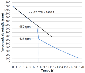
Figure1 is a plot created in Microsoft Excel using the table of results of an experience in which the servo let's the suspended discs fall when the discs below reach 1000 rpm.
Doing a linear regression between the deceleration and fall of the discs, it's possible to obtain the predicted rotational speed at the time that the falling discs stop sliding over the bottom discs.
Using the following quantities:
L - angular momentum
I - moment of inertia
ω - angular velocity
m - mass in rotation.
\[L_i=L_f\] \[I_i \omega_i=I_f \omega_f\] \[\frac{I_i}{I_f}=\frac{\omega_f}{\omega_i}\] \[\frac{\frac{m_i\left (r_1^2+r_2^2 \right )}{2}}{\frac{m_f\left (r_1^2+r_2^2 \right )}{2}}=\frac{\omega_f}{\omega_i}\] \[\frac{m_i}{m_f}=\frac{\omega_f}{\omega_i}\]
\[\frac{\omega_f}{\omega_i}=\frac{623}{950}=0,656\]
\[\frac{m_i}{m_f}=\frac{115}{115+69}=0,625\]
\[\frac{\left|0,656-0,625\right|}{\left|0,625\right|}\times 100=4,9\%\]
The speed ratio is different from the mass ratio by 4,9% which confirms the angular momentum conservation.
Protocol 2 - Moment of Inertia evaluation
5 discs with a total mass of 115g are accelerated by the hard-drive motor until they reach 1500rpm. In this moment the motor is disconnected, the discs rotate freely and their speed is read. When a certain speed that the user defines previously is reached, the relay puts each motor winding in parallel with a resistor which resistance is the same as the motor windings'. These resistors will dissipate energy acting as an electromagnetic brake.
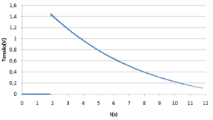
In the end of the session a table is provided with the disc speed and tension across one of the resistors function of time, whose values will be used in plots created in some program the user chooses.
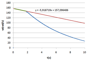
Figure2 and 3 are plots created in Microsoft Excel using the table of results of an experience in which the relay turns on when the rotating discs reach 1000 rpm.
The difference in the deceleration slope is clear. At first the discs are slowed only by the kinetic friction, but when the relay turns on, the resistors and motor windings are put in parallel and energy starts being dissipated through the resistors. The contribution of the resistors to the deceleration and consequently energy of the discs is given by the difference between the slopes.
Quantifying:
\[\frac{d\omega_{res}}{dt}=\frac{d\omega_{atrito+res}}{dt}-\frac{d\omega_{atrito}}{dt}=-194,860-(-79,234)=-115,626rpm/s = -115,626\times\frac{2\pi}{60}=-12,11rad/s^2\]
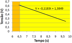
The kinetic friction must also be taken into account in the voltages, so that the energy dissipated by the resistors corresponds to the energy loss given by the difference between slopes. This can be done, adding the function adjusted to the first data series to the second and adjusting a new function.
To clarify, a voltage of 0,0241(t-6,42)V will be added to each point in the table of results after the time at which the relay turns on and a new function is adjusted to that data series. The result of this process is shown in Figure4.
Using the voltage given by the adjust function in Figure4 and knowing that the resistance is 5,3Ω in each of the 3 resistors, the dissipated power is calculated by:
\[P=VI=V\frac{V}{R}=\frac{V^2}{R}\]
The energy dissipated in the 3 resistors is obtained integrating the dissipated power over time:
\[\int_{6,67}^{9,62}\frac{dE}{dt}dt=3\int_{6,67}^{9,62}\frac{V^2}{R}dt=0,313J\]
The energy of a solid body in rotation and it's derivative is given by:
\[E=\frac{I\omega^2}{2}\;\;\;\;\;\;\;\;\;\;\frac{dE}{dt}=I\omega'\omega\]
The last equation is integrated knowing that \(\int_{6,67}^{9,62}\frac{dE}{dt}dt=-0,313J\) (the "-" is there because the energy is dissipated), ω' is constant = -12,11rad/s^2 (comes from the difference between slopes) and ω is given by the deceleration adjust function in rad/s,
\[\int_{6,67}^{9,62}\frac{dE}{dt}dt=\int_{6,67}^{9,62}I\omega'\omega \; dt\] \[-0,313=I(-12,11)\int_{6,67}^{9,62}\omega \; dt\] \[\frac{-0,313}{-12,11}=I\int_{6,67}^{9,62}-20,41t+230,93 dt\] \[I=\frac{-0,313}{-12,11\times 190,837}\] \[I=1,354\times 10^{-4}kg\, m^2\]
Now, the discs in this experience are in fact rings of interior and exterior radius 13mm and 47mm respectively. Their moment of inertia is then:
\[I=\frac{m\left(r_1^2+r_2^2\right)}{2}=\frac{0,115\left(0,013^2+0,047^2\right)}{2}=1,367\times 10^{-4}kg \; m^2\]
Evaluating the accuracy,
\[\frac{\left|1,354\times 10^{-4}-1,367\times 10^{-4}\right|}{\left|1,367\times 10^{-4}\right|}\times 100=0,9\%\]
The experimental results of this experience differ only 0,9% from the theoretical expectations!


