Difference between revisions of "Angular Momentum Conservation"
| Line 8: | Line 8: | ||
The aparatus also has a group of braking resistors that can be connected in parallel with the motor windings. This setup allows the realization of the second protocol, centered in the study of the moment of inertia. | The aparatus also has a group of braking resistors that can be connected in parallel with the motor windings. This setup allows the realization of the second protocol, centered in the study of the moment of inertia. | ||
| + | |||
| + | =Protocol1 - Angular Momentum Conservation= | ||
| + | |||
| + | [[File:Discos_velocidade_protocolo1.png|thumb|alt=|Figura1: velocidade de rotação]] | ||
| + | |||
| + | 5 discs with a total mass of 115g are acelerated by the hard-drive motor until they reach 1500rpm. In this moment the motor is disconnected, the discs rotate freely and their velocity is read. When a certain velocity that the user defines previously is reached, the servo let's 3 suspended discs with a total mass of 69g initially at rest fall on top of the o servo deixa cair sobre os discos em rotação 3 discos com 69g no total inicialmente em repouso. | ||
| + | |||
| + | No final da sessão obtém-se uma tabela com a velocidade dos discos em função do tempo, cujos valores servirão para criar um gráfico num programa ao critério do utilizador. | ||
| + | |||
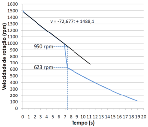
| + | A '''Figura1''' é um gráfico criado no Microsoft Excel a partir da tabela de resultados de uma experiência em que o servo deixa os discos cair a 1000 rpm. Fazendo uma regressão entre o início da desaceleração e a queda dos discos, obtém-se uma reta cuja equação nos permite determinar a velocidade prevista dos discos em rotação no ponto em que os discos que caem deixam de deslizar sobre os que estavam em rotação. | ||
| + | |||
| + | Usando as seguintes quantidades: | ||
| + | |||
| + | L - momento angular | ||
| + | |||
| + | I - momento de inércia | ||
| + | |||
| + | ω - velocidade angular | ||
| + | |||
| + | m - massa em rotação. | ||
| + | |||
| + | <div style="text-align: center;">Temos para a conservação do momento angular:</div> | ||
| + | \[L_i=L_f\] | ||
| + | \[I_i \omega_i=I_f \omega_f\] | ||
| + | \[\frac{I_i}{I_f}=\frac{\omega_f}{\omega_i}\] | ||
| + | \[\frac{\frac{m_i\left (r_1^2+r_2^2 \right )}{2}}{\frac{m_f\left (r_1^2+r_2^2 \right )}{2}}=\frac{\omega_f}{\omega_i}\] | ||
| + | \[\frac{m_i}{m_f}=\frac{\omega_f}{\omega_i}\] | ||
| + | |||
| + | <div style="text-align: center;">Obtém-se experimentalmente</div> | ||
| + | |||
| + | \[\frac{\omega_f}{\omega_i}=\frac{623}{950}=0,656\] | ||
| + | |||
| + | <div style="text-align: center;">enquanto que pela razão das massas</div> | ||
| + | |||
| + | \[\frac{m_i}{m_f}=\frac{115}{115+69}=0,625\] | ||
| + | |||
| + | <div style="text-align: center;">Fazendo um desvio à exatidão</div> | ||
| + | |||
| + | \[\frac{\left|0,656-0,625\right|}{\left|0,625\right|}\times 100=4,9\%\] | ||
| + | |||
| + | Conclui-se que a razão das velocidades (experimental) difere 4,9% da razão das massas (teórica), que está de acordo com a conservação do momento angular. | ||
Revision as of 10:25, 11 October 2012
UNDER CONSTRUCTION
Description of the Experiment
This control room allows the confirmation of angular momentum conservation and the measuring of the moment of inertia of rotating discs.
Experimental Apparatus
The experimental apparatus is based in a PC hard-drive to which were added a servo and a group of discs that the servo keeps above the rotating discs. This setup allows the realization of the first protocol, centered in the study of angular momentum conservation.
The aparatus also has a group of braking resistors that can be connected in parallel with the motor windings. This setup allows the realization of the second protocol, centered in the study of the moment of inertia.
Protocol1 - Angular Momentum Conservation
5 discs with a total mass of 115g are acelerated by the hard-drive motor until they reach 1500rpm. In this moment the motor is disconnected, the discs rotate freely and their velocity is read. When a certain velocity that the user defines previously is reached, the servo let's 3 suspended discs with a total mass of 69g initially at rest fall on top of the o servo deixa cair sobre os discos em rotação 3 discos com 69g no total inicialmente em repouso.
No final da sessão obtém-se uma tabela com a velocidade dos discos em função do tempo, cujos valores servirão para criar um gráfico num programa ao critério do utilizador.
A Figura1 é um gráfico criado no Microsoft Excel a partir da tabela de resultados de uma experiência em que o servo deixa os discos cair a 1000 rpm. Fazendo uma regressão entre o início da desaceleração e a queda dos discos, obtém-se uma reta cuja equação nos permite determinar a velocidade prevista dos discos em rotação no ponto em que os discos que caem deixam de deslizar sobre os que estavam em rotação.
Usando as seguintes quantidades:
L - momento angular
I - momento de inércia
ω - velocidade angular
m - massa em rotação.
\[L_i=L_f\] \[I_i \omega_i=I_f \omega_f\] \[\frac{I_i}{I_f}=\frac{\omega_f}{\omega_i}\] \[\frac{\frac{m_i\left (r_1^2+r_2^2 \right )}{2}}{\frac{m_f\left (r_1^2+r_2^2 \right )}{2}}=\frac{\omega_f}{\omega_i}\] \[\frac{m_i}{m_f}=\frac{\omega_f}{\omega_i}\]
\[\frac{\omega_f}{\omega_i}=\frac{623}{950}=0,656\]
\[\frac{m_i}{m_f}=\frac{115}{115+69}=0,625\]
\[\frac{\left|0,656-0,625\right|}{\left|0,625\right|}\times 100=4,9\%\]
Conclui-se que a razão das velocidades (experimental) difere 4,9% da razão das massas (teórica), que está de acordo com a conservação do momento angular.
