Light Polarization with multiple polarizers
Contents
Description of the Experiment
This experiment allows you to select the orientation up to five polarizers to interact with a source of polarize light from a red LED, ultimately measuring the incident power on a photocell. As such, the cascade of polarizers can be used to demonstrate the Malus law (classical electromagnetic theory) but as well the quantum explanation when it comes to a pile-up of single photons.
Polarizers have the property of absorbing the wave in one direction on that plane and remaining "transparent" in the other direction, such as "Polaroid" lenses. In the quantum interpretation, each polarizers acts as a measuring sensor as a single photon either passes or are absorbed by the medium, as described in the thought experiments of Dirac n-polarizers for the understanding the principle of quantum state superposition.
The aim of this experiment is to demonstrate the effect of light passing through those polarizers by interposing them in the light optical path at various angles defined by the user. For judicious angles, some counter intuitive results emerge...
Links
- Laboratory: Intermediate elab.tecnico.ulisboa.pt
- Control Room: Polaroide
- Grade: **
Who likes this idea
Experimental Apparatus
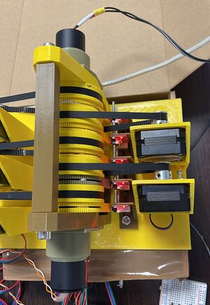
The apparatus consists on a light source (high bright red LED) passing a collimator, which focuses then the light rays into a parallel beam of light. At the beginning of the optical path, a vertical light polarizer is interposed, creating a source of polarized light.
In the optical path, the light travels through several polarized lenses without graduation, having the angle of the first been preset and being the other one free to rotate around the axis of propagation.
The light is finally collected through a converging lens into a photo-diode that measures the incident radiation intensity. This intensity is obviously the result of attenuation introduced by polarizing systems brought into its optical path.
A detailed description is available on a special page with instructions for the construction and assembly of this 3D printed experiment.
Protocol
In this control room we can measure the attenuation of a light beam caused by the cross-rotation of up to five polarized lenses. The light source is previously polarized.
The supervisor of the experiment can choose two sweep limits for one polarizer and set the angle of the other polarizers, acquiring the value of the transmitted power in a photo-diode.
The resolution (angle increment between two samples) is given by the step-motor minimum angle (1/200=1.8º) times the de-multiplication factor of the transmission, 1/5, giving 0.36º.
The LED power can be adjusted in order to have a broad resolution, be sure to select the appropriate power in order to avoid the non-linear region of the photo-diode circuit. Sometimes less is more.
Advanced protocol
The experience allows to be performed with starting with polarized light. Selecting this option the user can check the Malus's law in which multiple polarizers are used. In such case we need to multiply all the squares of the cosines between themselves, so the final value of the attenuation equation became:
[math] I_s = I_a \prod cos ^ 2 (\alpha_i) [/math]
were \( \alpha_i \) are the successive polarizers angles and \(I_a\) the initial light intensity.
In the case where two of the polarizers are at 90º between them, but the one between them is at an angle α, the sequential application of Malus' law leads to the following:
[math] I_s=I_a (cos (\alpha_i)cos(90-\alpha_i))^2=I_a (cos (\alpha_i)sen(\alpha_i))^2=\frac{I_a}{4}sen^2(2\alpha) [/math]
A paradox can arise from this, since if we have two polarizers at 90º no light will pass through, but by introducing a third polarizer between them at a proper angle such as 45º we already get light through the system, which will emerge attenuated (by 25% for 45º)!
Nonetheless, the interpretation of this phenomenon of the "repolarization" of light [1] necessarily has a quantum interpretation in the limit of a single photon. In this limit, the proposed experiment of the three consecutive polarizers can lead to a very interesting conclusion.
Note that every polarizer can have a systematic error. In the following table we provide a first clue of such angles, measured during assembly. Nevertheless a proper fit taking in consideration those errors can lead to a better estimation of the results.
| Polarizer order | Angle (º) |
|---|---|
| 1 | 33.48 ± 1 |
| 2 | 39.24 ± 1 |
| 3 | 33.84 ± 1 |
| 4 | 37.44 ± 1 |
| 5 | 37.08 ± 1 |


