Precision Pendulum Assembly: Electrical interfaces
Contents
Electrical interfaces
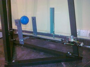
This section describes the electrical components used to operate the experimental apparatus. As an overview, each launcher consists of:
- a Raspberry Pi (or computer running Linux): makes the interface between the micro-controller and the human (e.g., direct connection to a console) or e-lab server via Internet.
- a micro-controller (dsPic): makes the interface between the electrical components (including the step-motor) and the computer.
- electrical components: laser, micro-switch, photo-gate (or photo-diode), light bulb, temperature sensor, etc... see Parts for detailed description. These components connect directly to the micro-controller while providing ways of controlling the pendulum apparatus and bringing measurement capabilities.
See the Connections subsection for details on how to connect the electrical components.
The photo-gate/photo-diode and laser alignment is described in subsection Photo-gate and laser alignment. This is to be performed only after the micro-controller has been powered up, read section Interface console to micro-controller first.
Parts
This subsection presents a description of the different electrical parts of the experiment.
- Raspberry Pi (RPi): Device running Linux to allow remote connection to the experiment as well as an easy way to interface with the micro-controller. The present micro-controller and corresponding flat cable connections are designed for the Raspberry Pi 3 Model B, which has the following pin-out connections as described in https://www.raspberrypi.org/documentation/usage/gpio. If the Raspberry Pi is used to also power the micro-controller, a +5 V power supply with at least 2.5 A should be used.
- SD card: The SD card comes with Linux operating system and all necessary additional programs.
- micro-controller board: This board contains a micro-controller (dsPic33F) as well as all peripheral components needed for the control of the experiment. The board can be powered using the flat cable connected to the Raspberry Pi or by a USB connection (an onboard jumper is used to select the power source, the default position corresponds to the one from the flat cable).
- webcam: The webcam is used to provide live video streaming during the execution of the experiment. It is connected to the Raspberry Pi via an USB cable. The RPi performs the encoding and then sends it through Internet.
- light bulb: The light bulb consists of a 12 V LED bulb located above the launcher. This bulb turns on during the execution of the experiment to illuminate the pendulum and launcher (especially useful if the experiment is performed during the night).
- step-motor: The step-motor is part of the launcher and it is controlled by the micro-controller via a quad 1/2 H bridge driver. The step-motor is responsible by the displacement of the shovel.
- micro-switch: The micro-switch is located at the origin, close to the 0 cm of the metric scale on the launcher. It used to indicate the micro-controller that the shovel reached the origin and cannot go further in the backward direction (end of course).
- laser: The laser is located approximately at the center of the launcher. In conjunction with the photo-gate/photo-diode, the laser is used to measure the oscillation period as well as the location of the shovel. On power-on the laser is set ON to allow the verification of the photo-gate alignment. It should be performed a "local start" in order to leave the microcontroller in Stand-by mode, bringing the laser to a OFF state.
- photo-gate (or photo-diode): The photo-gate is located in front of the laser. The ball travels in-between interrupting the light from the laser periodically.
- temperature sensor: A temperature sensor is located in the DB25 box to measure the ambient temperature. The ambient temperature influences the length of the pendulum cable. It is therefore important to monitor this quantity.
- display: The display shows the total accumulated number of oscillations. It consists of 8 digits, each one a 7 segments display.
- power supply: The step-motor requires a +12 V power supply capable of providing 2 A (maximum). Note that the microcontroller unit is feed by 5V coming from the Raspberry through the flat cable not from this unit.
- start button: The start button allows to locally start an experiment with a predefined configuration (initial displacement of 10 cm during 20 oscillations).
Connections
Photo-gate and laser alignment
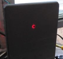
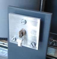
The photo-gate and laser alignment can only be performed once the micro-controller has been turned on and it is communicating with a console. See subsection Interface console to micro-controller on how to power on the micro-controller and how to control the laser. The alignment consists of pointing the laser into the hole of the photo-gate structure, as shown below in the figure on the left. The laser orientation can be adjusted using the 3 screws from its holding support structure, figure on the middle.
The laser should come from factory correctly focused; nevertheless it's focus can be refined if needed by using a proper white sheet and rotating the laser lens to bring a focus diameter below 1mm at ~150mm focal plane.
The procedure for the alignment consists on the following steps:
- Turn on the laser using the "laser on" command
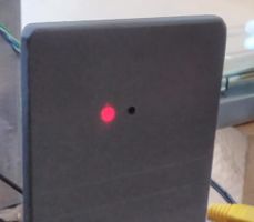
- If necessary, adjust the laser orientation so that its light goes into the photo-gate structure hole (figure on the left). An example of misalignment is shown in the figure on the right.
- Perform the Laser and photo-gate test

|

|

|
Electric tests
- Test the micro-switch with the help of a multimeter (ohmmeter). When released it should present a very high impedance (order of MOhm) and when pressed it should present a very low impedance (like a shunt, ~0 Ohm). Perform the measurement at the DB25 pins: between pins no. 3 and 4.
- Check voltage of step-motor power supply to ensure that it is not higher than +12 V.
Gate system
To avoid a long run of the experiment to achieve a reasonable period accuracy readout with a normal chronometer one could use instead of a gated photo-detector connected to an acquisition system or to a precision pulse counter.
The World Pendulum design can be easily adapted as it consists on a photodiode mounted in a aluminium (or PVC) holder (20x20x6 mm3) with a central 1,5mm hole and a 4mm cavity on the back side(see design) where is fixed the photodiode with a black plastic wax.
In front of the photodiode, a solid-state laser beam from a normal pointer device is used to trigger the counter once the ball hide the light.
