Precision Pendulum
An accurate pendulum is easy to construct once we get the right materials. The World Pendulum was design in a very robust way but a simplified version with common materials is described here.
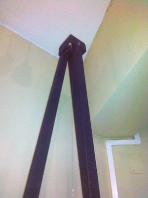
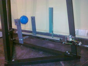
The basic support can be a wall or a robust metallic structure like the one presented here. The choice for the mass was a training steel weight from the official shot put with 2kg. This weight has the advantage of having a drilled hole for holding a M4 screw and can be find in any good sports shop. This screw can be made of a threaded brass rod with 10mm length. A small 1mm hole is drilled on the rod were the pendulum string is soldered using current soldering thin-plumb(or any silver-thin alloy). The string used is from 0.4mm remanium wire that can be bought in any dentistry retailer. The other end is soldered to the same brass rod with a length of 50mm, using the same technique (1mm hole and soldering).
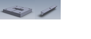
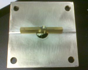
The support for the fulcrum is made from any robust plane surface as for instance a brass or stainless steel piece with a 12-16mm hole. This surface have a scratch made with a diamond or hard steel blade were the pivot work. With this design slipper is avoid.
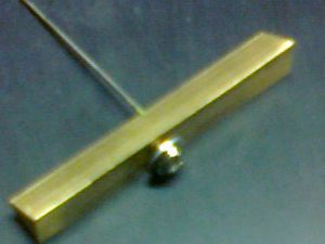
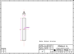
The fulcrum itself is made as well of stainless steel or brass consisting in a triangular prism with 50mmx9mm with a central 1mm hole in one face crossing the opposite edge. In this hole is soldered a intravenous needle were the pendulum string is glued or soldered.
Contents
Mechanical assembly
There are two types of mechanical assemblies:
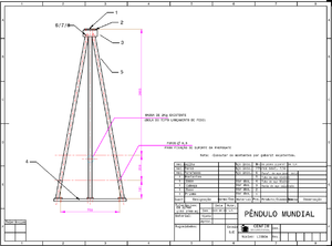
- Tripod independent metallic structure
- Wall fixed launcher and pendulum top holder
Parts (support structure)
Order of assembly and filling with sand
Drawings
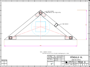
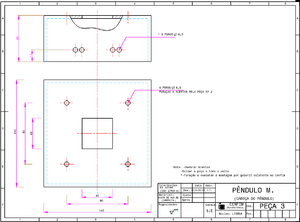
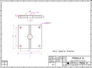
The following drawings document the construction of the metallic pendulum's sections.
Electrical interfaces
This section describes the electrical components used to operate the experimental apparatus. As an overview, each launcher consists of:
- a Raspberry Pi (or computer running Linux): makes the interface between the micro-controller and the human (e.g., direct connection to a console) or e-lab server via Internet.
- a micro-controller (dsPic): makes the interface between the electrical components (including the step-motor) and the computer.
- electrical components: laser, micro-switch, photo-gate (or photo-diode), light bulb, temperature sensor, etc... see Parts for detailed description. These components make the interface between the experimental apparatus and the micro-controller while providing ways of controlling the pendulum as well as measurement capabilities.
See the Connections subsection for details on how to connect the electrical components.
The photo-gate/photo-diode and laser alignment is described in subsection Photo-gate and laser alignment. This is to be performed only after micro-controller has been powered up, read subsection # first.
Parts
Connections
Photo-gate and laser alignment
Electric tests
Calibration
String measurement
The pendulum accuracy depends strongly in its rigorous length measurement (~2,700 m) with less than 0,5 mm. Indeed this is the crucial factor to achieve the desired 0,02% accuracy and for that propose a well calibrated measuring tape as to be chose. If this method is adopted special care as to be taken to avoid parallax. Alternative methods like ultrasonic measurement with laser targeting are the best, using a metallic or marble stone plane fitted tangential to the weight (allowing it to roll but touching the plane). With this method a few takes shall be done surrounding the ball and their average value will be considered the pendulum reference length.
Recalibration of the length as to be pursuit every month to guarantee a reasonable precision.
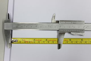
In the figure is shown how to correct the measuring tape initial offset by careful eliminating the systematic error from the contact with the sphere.
Plane of oscillation
Floor parallelism from top and bottom triangles
Bob movement given by fulcrum excitation
Interface console to micro-controller
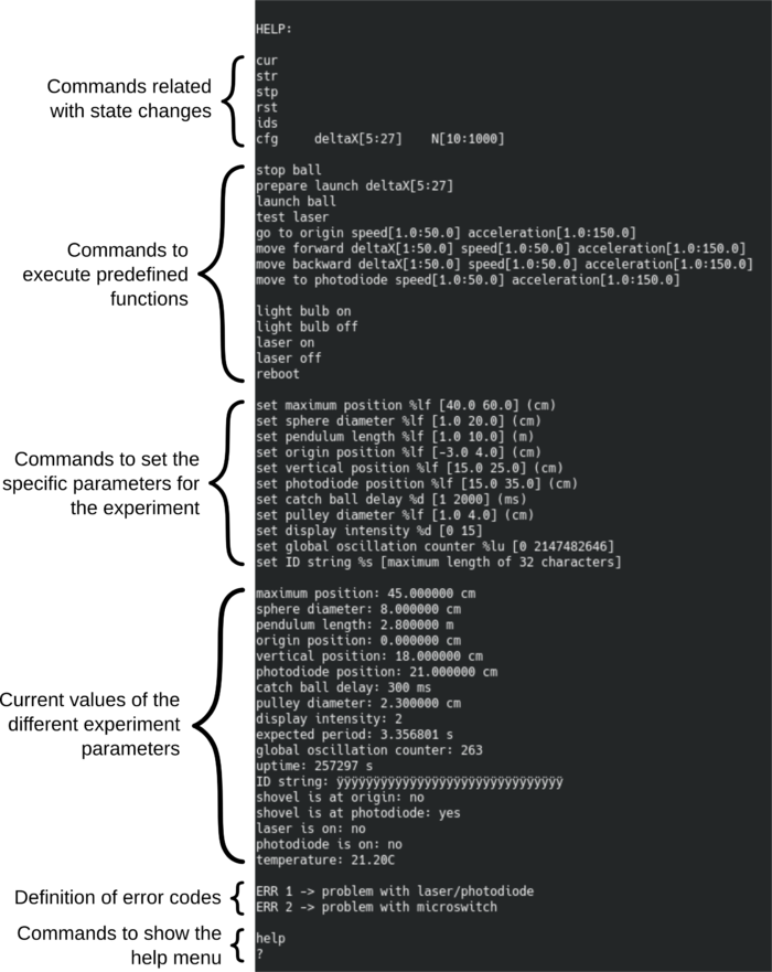
The micro-controller provides a menu that allows the user to set the parameters of the experiment and run predefined functions to allow configuration and testing. The interface between user and micro-controller is performed via the RS-232 serial connection with the following parameters:
   • Baud-rate: 115200 bps
   • Parity: No
   • Data bits: 8
   • Stop bits: 1
As an example, the “minicom” console interface can be used to communicate with the micro-controller. In the RaspberryPi, this interface can be called from a shell using the following command:
minicom -D /dev/ttyS0
or
minicom -D /dev/ttyAMA0
The “/dev/ttyS0” or "/dev/ttyAMA0" is the device (micro-controller) location. The minicom program will create a serial connection with default parameter which, in principle, are the same as the ones mentioned above. If not, check the help page of the minicom program (type "man minicom") to see how to set those parameters. After launching the program, be sure to add a line feed so that the messages sent by the micro-controller appear in new lines. In minicom, the line feed is activated/deactivated by pressing Ctrl+a followed by a. Once the communication (connection) is established, it is possible to access the micro-controller menu by sending:
? (question mark followed by an enter hit)
or
help (“help” followed by an enter hit)
The output will be similar to the one shown in the following figure:
Every command should be followed by a carriage return – “\r” (hit enter) so that the micro-controller can process the sent string. Hitting enter also clears the micro-controller input buffer, so it can also be used for that purpose. The words in the commands are separated by one space character only except for the “cfg deltaX[…] N[...]” command where the words/inputs are separated by one tab character “\t”.
The “[ ]” (square brackets) in the commands define the range of accepted input values. The numeric representation of these limits indicate the type of accepted value, i.e., integer or float. If the limit value contains a decimal case, the accepted values for that parameter are float. If the limit value does not contain a decimal case, the accepted values are integer only. See the following examples:
   cfg    deltaX[5:25]    N[10:1000]                                      ->    cfg    15    30
   set maximum position %lf [40.0 60.0] (cm)                              ->    set maximum position 47.7
   set catch ball delay %d [1 2000] (ms)                                  ->    set catch ball delay 300
   set pulley diameter %lf [1.0 4.0] (cm)                                 ->    set pulley diameter 2.356
   set ID string %s [maximum length of 32 characters]                     ->    set ID string WORLD_PENDULUM_LISBON
   cur                                                                    ->    cur
   go to origin speed[1.0:50.0] acceleration[1.0:150.0]                   ->    go to origin 11.5 41.1
   move forward deltaX[1:50.0] speed[1.0:50.0] acceleration[1.0:150.0]    ->    move forward 4.5 2.2 2.0
Before turning the micro-controller on, it is important to perform two position measurements (maximum and vertical). The procedure to measure these positions is described in Setting specific parameters for the experiment.
Commands related with the state machine and communication with e-lab driver (Java program running in the RaspberryPi):
- cur: Ask the micro-controller about its current configuration.
- str: Change the micro-controller state to STARTED and starts an experiment if previously configured using a "cfg" command.
- stp: Stops an experiment and send the micro-controller to the STOPED state.
- rst: Resets the micro-controller and send it to the RESET state.
- ids: Ask the micro-controller to send an its identifications. E.g.: IDS WP_LIS STOPED
- cfg: Send the configuration for a new experiment. This command accepts two integer parameters: 1st - initial displacement in cm, 2nd - number of oscillations
Commands to execute predefined functions, useful for calibrations and testing:
- stop ball: This command is used to stop the ball from oscillating. After stopping the ball, the shovel resting position is at the photo-diode/photo-gate.
- prepare launch: This command accepts one integer which corresponds to the initial displacement (maximum amplitude) before releasing the ball. The command displace the shovel to the required position and rests at that position.
- launch ball: This command released the ball by sending the shovel to the origin at its maximum speed.
- test laser: This function is used to simultaneously test the laser and the photo-gate/photo-diode. A more detailed description of this command is found in Laser and photo-gate test as well as procedures to check in case of a failed test.
- go to origin: This command accepts two inputs: 1st - speed in cm/s (double) and 2nd - acceleration in cm/s² (double). It sends the shovel to the origin (until it reaches the micro-switch).
- move forward: This command accepts three inputs: 1st - horizontal displacement in cm (double), 2nd - speed in cm/s (double) and 3rd - acceleration in cm/s² (double). It moves the shovel in the forward direction (away from the origin).
- move backward: This command accepts three inputs: 1st - horizontal displacement in cm (double), 2nd - speed in cm/s (double) and 3rd - acceleration in cm/s² (double). It moves the shovel in the backward direction (towards the origin).
- go to photodiode: This command accepts two inputs: 1st - speed in cm/s (double) and 2nd - acceleration in cm/s² (double). It sends the shovel to the photo-diode/photo-gate if the shovel is beyond the photo-diode/photo-gate in the forward direction. If the shovel is between the photo-diode and the origin the command sends the shovel to the origin (until it reaches the micro-switch).
- light bulb on: Turns the light bulb on to illuminate the experiment.
- light bulb off: Turns the light bulb off.
- laser on: Turns the laser on.
- laser off: Turns the laser off.
- reboot: Performs a software reset to the micro-controller. Before resetting, the micro-controller stores the current number of oscillations into the flash memory.
Commands to set the specific parameters for the experiment (see section Setting specific parameters for the experiment for more details) and stores them in the flash memory so that they are not lost in case of a power down situation:
- set maximum position: Stores the shovel maximum absolute allowed position in cm (where it is mechanically impossible to go further in the forward direction).
- set sphere diameter: Stores the sphere diameter in cm and measured at the equatorial plane.
- set pendulum length: Stores the length of the pendulum. See String measurement for details on how to measure the string length. IMPORTANT: the pendulum length should include the radius of the ball.
- set origin position: Stores the position of the shovel when located at the origin, i.e., when the shovel is stopped by pressing the micro-switch.
- set vertical position: Stores the position of the shovel when the pendulum (ball + string) is perfectly vertical.
- set photodiode position: Stores the position of the shovel when located at the photo-doide/photo-gate location.
- set catch ball delay: Stores the delay used to catch (stop) the ball when this one is oscillating with a relatively large amplitude.
- set pulley diameter: Stores the diameter of the pulley attached to the step-motor. This value is used to calibrate the displacement of the shovel.
- set display intensity: Stores the display light intensity. This value should be set so that the numbers are visible/readable on the live video stream when the experiment is running, i.e., when the light bulb is on. 0 is the lowest intensity and 15 is the maximum one.
- set global oscillation counter: Stores the number of total global oscillations. It is also used to override/reset the counter.
- set ID string: Sores the experiment identification string (name of the experiment). The string is limited to a maximum of 32 characters.
Current values/parameters for information:
- expected period: Shows the expected oscillation period in seconds. This value is calculated with the pendulum length and it essential for the proper operation of the experimental apparatus.
- uptime: Shows the time in secdons since the micro-controller was powered up.
- shovel is at origin: Indicates if the shovel is located at the origin (yes/no).
- shovel is at photodiode: Indicates if the shovel is located at the photo-diode/photo-gate (yes/no).
- laser is on: Indicates if the laser is switched on (yes/no).
- photodiode is on: Indicates if the photo-diode/photo-gate is lit (conducting state) or dark (non-conduction state). The output is yes/no.
- temperature: Indicates the temperature in degrees Celsius. The temperature sensor is located in the DB25 box connected to the micro-controller board.
- ERR 1: Indicates that there is a problem with the laser or photo-diode/photo-gate. See Laser and photo-gate test for more details and debug procedures.
- ERR 2: Indicates that there is a problem with the micro-switch. See Connections to double check that the micro-switch is properly connected.
Laser and photo-gate test
The micro-controller has a dedicated function (accessible from the console menu) to test the laser and photo-gate simultaneously. This function consist of blinking the laser 5 times with a full period of 100 ms (500 ms total). If the photo-gate correctly detects the laser state the test will be successful. To manually run the laser and photo-gate test, just type the “test laser” command in the console. During booting, the micro-controller runs the laser and photo-gate test function to ensure that both components are working properly. If the test fails, the micro-controller returns the “ERR1” error code. This error can be associated with one or more of the following possible problems:
- Wrong electrical connections: Check section Connections to ensure the both laser and photogate are properly connected to the micro-controller.
- Laser and photo-gate misalignment: Check if the laser light is properly pointed to the photo-gate structure hole and adjust as described in section Photo-gate and laser alignment if needed.
- The photo-gate is always closed (conducting): If the ambient light is too intense or if some source of light other than the laser is going through the photo-gate structure hole with enough intensity, it can happen that the photo-gate is always conducting making it impossible to the micro-controller to distinguish between laser ON and OFF states. In this case, the solution is to reduce the ambient light or change the experiment orientation so that the photo-gate receives less light.
After trying to correct the possible source of errors, re-run the test to check if the problem is solved.
Setting specific parameters for the experiment
Two of the settable parameters need to be measured with the micro-controller turned off (powered off). These two parameters are:
Local gravity (comparison with on-line calc tipo https://www.sensorsone.com/)
Non-remote usage
For local use the gate system can drive a up/down counter. Currently we have adopted the Velleman multifunction up/down counter kit K8035 avaiable off-the-shelf. The connection to the photo-diode is done via the VCC to the UP channel (pin 9) using just the first (R14) 2,2k resistor and eliminating the protection circuit in the transistor's gate (ZD1, R15 and R18).
The device should operate with Long debounce enable. Moreover we can use the regulated power supply (5V) in series with a 33 Ohms resistor to feed the photogate's laser pointing device.
Gate system
To avoid a long run of the experiment to achieve a reasonable period accuracy readout with a normal chronometer one could use instead a gated photo-detector connected to an acquisition system or to a precision pulse counter.
The World Pendulum design can be easily adapted as it consists on a photodiode mounted in a aluminium (or PVC) holder (20x20x6 mm3) with a central 1,5mm hole and a 4mm cavity on the back side(see design) where is fixed the photodiode with a black plastic wax.
In front of the photodiode a solid-state laser beam from a normal pointer device is used to trigger the counter once the ball hide the light.
Partners
Mechanical structures in suport of high schools replicas have been assembled and constructed with the kind help of CENFIM, Lisbon.

