Difference between revisions of "Angular Momentum Conservation"
| Line 57: | Line 57: | ||
The speed ratio is different from the mass ratio by 4,9% which gives a good approximation for the angular momentum conservation. | The speed ratio is different from the mass ratio by 4,9% which gives a good approximation for the angular momentum conservation. | ||
| + | If we know the exact dimensions of the disks ($r_1=, r_2=$), adding a error momentum on the equations we can inferred an approximated value for the motor rotor momentum of inertia (or its mass knowing its average radius). | ||
=Advanced Protocol - Moment of Inertia Evaluation= | =Advanced Protocol - Moment of Inertia Evaluation= | ||
Revision as of 10:23, 12 January 2013
UNDER CONSTRUCTION
Contents
Description of the Experiment
This control room allows the confirmation of angular momentum conservation by colliding a spinning disk with another. Moreover, the disk inertia momentum can be extrapolated from energy conservation principles.
Experimental Apparatus
The experimental apparatus is based in a PC hard disk drive motor and its spinning disk. A second disk is held on top of it and can be dropped by a servo motor actuator.
The apparatus´ motor can be used as a generator equipped with a switchable resistor acting as an electromagnetic brake. The braking current&voltage characteristic is measured allowing a rigorous energy dissipation calculation.
Protocol - Angular Momentum Conservation
A disc with a total mass of 115g is accelerated by the hard-drive motor until they reach a selected angular velocity. In this instant the motor is disconnected from supply and the disc allowed to rotate freely being their speed monitored. When a certain pre-determined speed is reached, the servo lets the suspended disc with a total mass of 69g initially at rest fall on top of the rotating disc.
Data taken from the experiment is given and plotted with the disc speed in function of time.
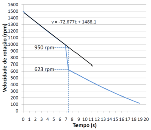
Figure1 is a plot using the table of results of an experience in which a servo lets the suspended disc fall when the disc below reach 1000 rpm.
If we do a linear regression between the deceleration and fall of the disc, it's possible to obtain the predicted rotational speed at any time. This give us the thumb rule for the friction deceleration related to angular speed.
Physics
Using the following quantities:
L - angular momentum
I - moment of inertia
ω - angular velocity
m - mass in rotation.
For the angular momentum conservation:
$L_i=L_f$
$I_i \omega_i=I_f \omega_f$
$\frac{I_i}{I_f}=\frac{\omega_f}{\omega_i}$
$\frac{\frac{m_i\left (r_1^2+r_2^2 \right )}{2}}{\frac{m_f\left (r_1^2+r_2^2 \right )}{2}}=\frac{\omega_f}{\omega_i}$
$\frac{m_i}{m_f}=\frac{\omega_f}{\omega_i}$
The experimental results give:
$\frac{\omega_f}{\omega_i}=\frac{623}{950}=0,656$
while the predicted mass ratio is
$\frac{m_i}{m_f}=\frac{115}{115+69}=0,625$
Evaluating the accuracy:
$\frac{\left|0,656-0,625\right|}{\left|0,625\right|}\times 100=4,9\%$
The speed ratio is different from the mass ratio by 4,9% which gives a good approximation for the angular momentum conservation. If we know the exact dimensions of the disks ($r_1=, r_2=$), adding a error momentum on the equations we can inferred an approximated value for the motor rotor momentum of inertia (or its mass knowing its average radius).
Advanced Protocol - Moment of Inertia Evaluation
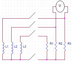
A disc with a total mass of 115g are accelerated by the hard-drive motor until they reach a pre-defined angular velocity. In this moment the motor is disconnected and the disc allowed to rotate freely. When a certain speed that the user defines previously is reached, a relay puts each motor winding in parallel with a resistor which resistance is the same as the motor's windings. These resistors will dissipate energy acting as an electromagnetic brake. This energy can be accounted and using the table values provided (disc speed and voltage across the resistors)in function of time.
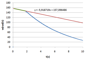
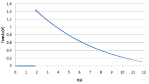
Figures 2 and 4 are plots created in Microsoft Excel using the table of results of an experience in which the relay turns on when the rotating discs reach 1400 rpm.
Using the first data to do a linear regression it is possible to get the speed of the motor over time if the relay didn't turn on.
Quantifying:
\[\frac{d\omega_{res}}{dt}=\frac{d\omega_{atrito+res}}{dt}-\frac{d\omega_{atrito}}{dt}=-194,860-(-79,234)=-115,626rpm/s = -115,626\times\frac{2\pi}{60}=-12,11rad/s^2\]
The kinetic friction must also be taken into account in the voltages so that the energy dissipated by the resistors corresponds to the energy loss given by the difference between slopes. This can be done adding the function adjusted to the first data series to the second and adjusting a new function.
To clarify, a voltage of 0,0241(t-6,42)V will be added to each point in the table of results after the time at which the relay turns on and a new function is adjusted to that data series. The result of this process is shown in Figure4.
Using the voltage given by the adjust function in Figure4 and knowing that the resistance is 5,3Ω in each of the 3 resistors, the dissipated power is calculated by:
\[P=VI=V\frac{V}{R}=\frac{V^2}{R}\]
The energy dissipated in the 3 resistors is obtained integrating the dissipated power over time:
\[\int_{6,67}^{9,62}\frac{dE}{dt}dt=3\int_{6,67}^{9,62}\frac{V^2}{R}dt=0,313J\]
The energy of a solid body in rotation and it's derivative is given by:
\[E=\frac{I\omega^2}{2}\;\;\;\;\;\;\;\;\;\;\frac{dE}{dt}=I\omega'\omega\]
The last equation is integrated knowing that \(\int_{6,67}^{9,62}\frac{dE}{dt}dt=-0,313J\) (the "-" is there because the energy is dissipated), ω' is constant = -12,11rad/s^2 (comes from the difference between slopes) and ω is given by the deceleration adjust function in rad/s,
\[\int_{6,67}^{9,62}\frac{dE}{dt}dt=\int_{6,67}^{9,62}I\omega'\omega \; dt\] \[-0,313=I(-12,11)\int_{6,67}^{9,62}\omega \; dt\] \[\frac{-0,313}{-12,11}=I\int_{6,67}^{9,62}-20,41t+230,93 dt\] \[I=\frac{-0,313}{-12,11\times 190,837}\] \[I=1,354\times 10^{-4}kg\, m^2\]
Now, the discs in this experience are in fact rings of interior and exterior radius 13mm and 47mm respectively. Their moment of inertia is then:
\[I=\frac{m\left(r_1^2+r_2^2\right)}{2}=\frac{0,115\left(0,013^2+0,047^2\right)}{2}=1,367\times 10^{-4}kg \; m^2\]
Evaluating the accuracy,
\[\frac{\left|1,354\times 10^{-4}-1,367\times 10^{-4}\right|}{\left|1,367\times 10^{-4}\right|}\times 100=0,9\%\]
The experimental results of this experience differ only 0,9% from the theoretical expectations!


